





NANO.WIKI

Understand the physics. Confirm it with measurements.

A coating about one millimetre thin as thermal protection sounds unusual at first. That is why we would rather not ask anyone to simply take our word for it. NANO.WIKI explains the physical properties of the system, shows the technical evidence behind them, and sets out what has actually been measured on complete building elements.

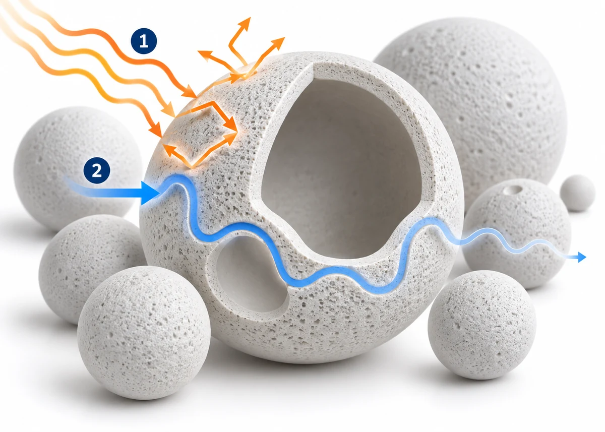
A hollow ceramic nanosphere shown in section among further spheres: heat radiation is reflected at the surface, while heat conduction takes a longer path around the cavities.

This wiki is maintained by Markus G. Schlegel, DEKRA-certified real estate appraiser (D2). Every figure states its source and its date.

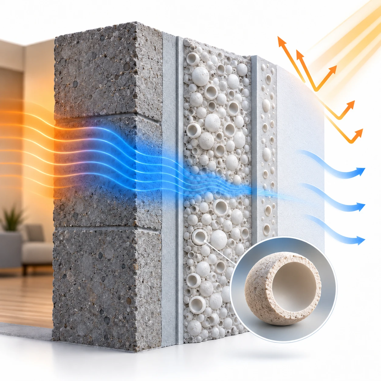
Section through a solid wall with primer, functional layer and top coat, the latter two with ceramic hollow bodies: the heat flow from inside becomes narrower within the coating, the sun’s rays are thrown back at the outer surface, and heat passes from the surface to the surroundings.
Sectional drawing, not to scale — the coating is about one millimetre thin.

The heat barrier – the principle at a glance

Nano facade insulation does not act at one single place, but as a multi-layer coating system.

Ceramic hollow bodies in the coating layers limit heat conduction in the material. The outer surface reflects a large part of the incoming solar energy.

We call this interplay the heat barrier. How strongly the complete system acts on the building element is not only explained in what follows, but traced through manufacturer data and measurements.

  1. 01 Simply explained What happens?
  2. 02 Understand the physics Why can this work?
  3. 03 Confirmed by measurements What has actually been demonstrated?

Simply explained

Nano facade insulation addresses two of the paths along which heat reaches or crosses a facade: solar radiation and conduction in the material. The heat barrier is therefore not a single layer, but acts at two different places.

  1. 1

    The sun strikes the wall

    In summer, solar radiation falls on the facade. An ordinary surface absorbs a large part of it and warms up; that heat then travels on inwards. The top coat throws most of the radiation back before it is absorbed at all.

    Here the barrier is the surface itself. Solar energy that is reflected away does not need to be insulated against in the first place.

  2. 2

    Heat travels through the material

    In a solid material, particle lies against particle. Heat passes from one to the next along a short, continuous path — that is heat conduction. The coating is not solid: it is densely filled with hollow ceramic spheres, and between them the continuous solid is gone.

    Here the barrier is not a surface but a detour: the heat has to go around every cavity, countless times over. In addition, according to the manufacturer, the Knudsen effect applies: in such small cavities the gas molecules collide with the wall rather than with each other and therefore transport considerably less heat.

Two paths, two places — and not one of them is a thick layer. That is precisely why the effect cannot be read off the thickness.

Understand the physics

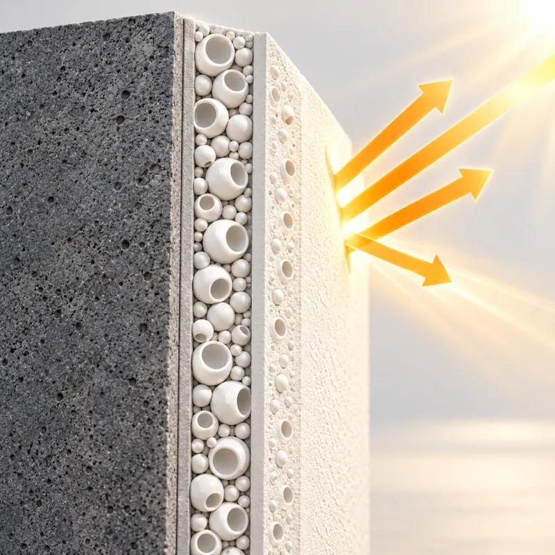
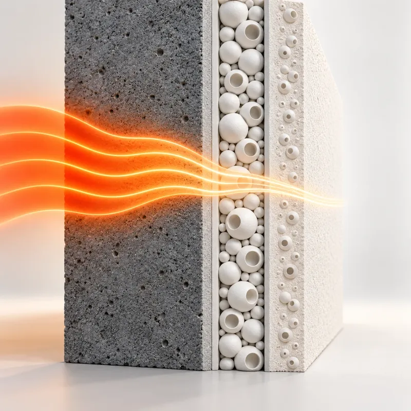
Sectional drawing, not to scale — the coating is about one millimetre thin.

Two places where the system acts

At the surface, it is about the sun. Its radiation is short-wave; the top coat throws a high share of it back — this is described by the total solar reflectance. Only the solar energy arriving from outside is meant, not the heat the wall gives off itself.

Inside the material the subject is conduction. Heat conduction needs continuous contact; where the solid is interrupted, the short path breaks off. The hollow ceramic spheres in the functional layer and the top coat are exactly those interruptions. How much this amounts to in total cannot be derived from the principle alone — that is what the manufacturer’s characteristic values and the measurement on the finished element are for.
Do not compare thickness — examine the effect.

Conventional insulation materials achieve their thermal protection mainly through the high thermal resistance of a comparatively thick layer. Nano facade insulation is a different coating system. What matters is therefore not how many millimetres equal how many centimetres, but what thermal effect the complete build-up actually achieves under defined conditions.

And the physics behind it is not new: very small pores that influence the heat transport of the enclosed gas are familiar from aerogel. Extremely thin coatings that reflect a large part of solar radiation are familiar from solar control glass. That an overall effect arises from the interplay of several components is familiar from modern insulating glass.

Confirmed by measurements

Each area stands on its own: with its characteristic value and its evidence.

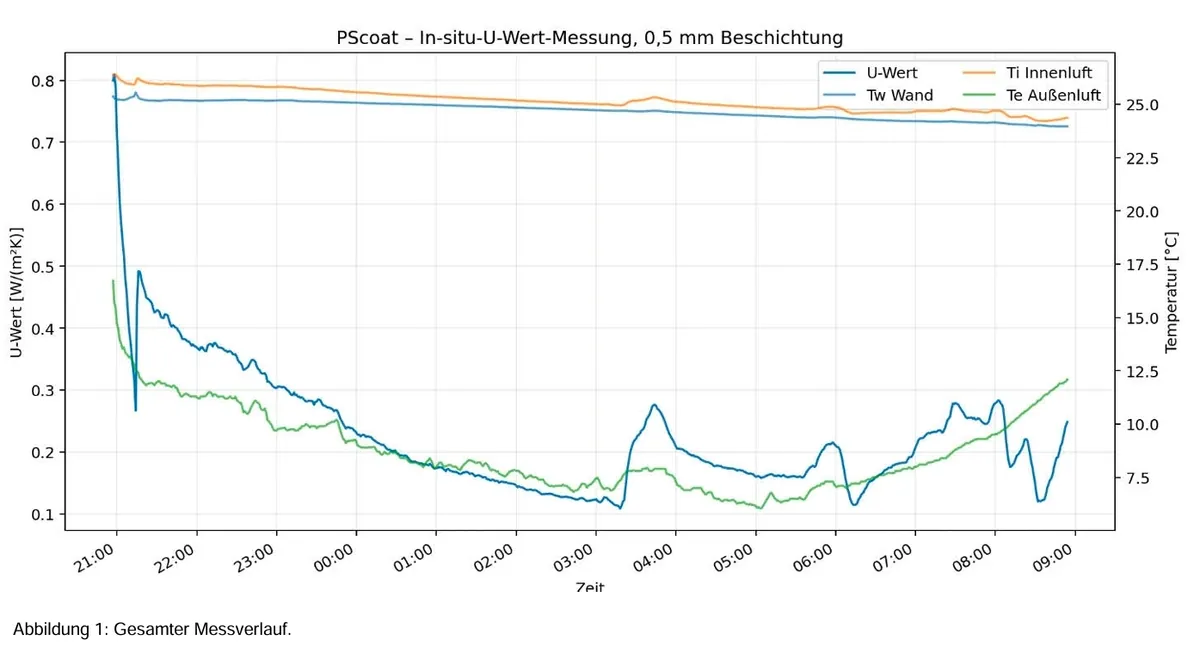
Overall effect on the building element · historic solid wall, evaluation window 01:15–03:15 · Testo 635-2 · 11 h 57 min

01

Limiting heat conduction

The material structure limits heat transport within the coating. For the complete system build-up the manufacturer declares an equivalent lambda.

Documented

Both coating layers contain ceramic hollow bodies; where the solid is interrupted, the short path of heat conduction breaks off. For the complete system build-up the manufacturer declares an equivalent lambda of 0.00012 W/(m·K) at 1 mm layer thickness; that corresponds to a thermal resistance of 8.3 m²K/W. Of that, a plate test to PN-EN 1745 captures only conduction through the material (0.0324 W/(m·K)); the system value goes far beyond it — it is a calculated value from the manufacturer.

Characteristic values

  • λ 0,00012 W/(m·K) Equivalent system value, 1 mm thickness Source: Herstellererklärung – Wärmeleitfähigkeit (Lambda) je Schichttyp · Version 1.0, 10.07.2026 · Method: äquivalenter Systemwert bei 1 mm Schichtdicke, entspricht R = 8,3 m²K/W View evidence →

What this shows

  • The manufacturer declares an equivalent lambda of 0.00012 W/(m·K) for the complete system build-up at 1 mm.
  • Both coating layers contain ceramic hollow bodies and are functional parts of the system — the top coat is not merely a protective layer.
  • Conduction through the material alone is tested to PN-EN 1745; it explains only a small part of the system value.
02

Reflecting solar energy

The outer surface reflects a high proportion of incoming solar radiation. The facade therefore absorbs less solar energy.

Documented

When solar radiation strikes a facade, part of it is reflected and part is absorbed by the surface. The absorbed share warms the facade and can then be passed on into the building element as heat. The top coat throws a high proportion back at the surface itself — solar energy that never reaches the wall does not need to be insulated against. This refers exclusively to solar energy arriving from outside.

Characteristic values

  • TSR 92 % Top coat Source: CE-Kennzeichnung PSC 250 T · Version 04/2026 · Method: Hotbox, TÜV-bestätigt View evidence →

What this shows

  • A high proportion of incoming solar radiation is reflected.
  • This limits the solar warming of the facade surface.
  • It matters above all for summer thermal comfort.
03

Overall effect on the building element

A very low rate of heat flow was determined on a real historic solid wall over almost twelve hours.

Measured on the element

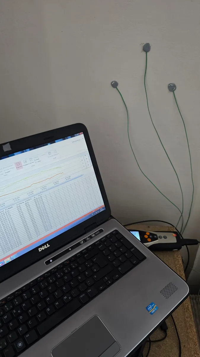
The two areas explain why the coating can act thermally. What matters, however, is what arrives at the finished wall — and that cannot be calculated by adding up the individual properties. During a continuous measurement on an inhabited historic solid wall with roughly 0.5 mm of coating, 42.978 data records were logged over 11 h 57 min. In the stable evaluation window from 01:15–03:15, the U-value determined averaged 0.140 W/(m²K); across the entire later measuring phase it was 0.195 W/(m²K).

Characteristic values

  • U 0,140 W/(m²K) historic solid wall, evaluation window 01:15–03:15 Source: In-situ-Messung PSC-U-2026-001, Testo 635-2 · Version 06./07.09.2026 · Method: In-situ-Ermittlung mit Testo 635-2 und U-Wert-Kit View evidence →

What this shows

  • A very low rate of heat flow was determined on the element examined, under documented conditions.
  • The value does not come from a single reading but from a complete measurement series.
  • A measurement error identified at the start was documented and excluded from the evaluation.

Transparency is part of the evidence.

Well documented

  • Thermal function of both coating layers
  • Thermal conductivity of the material to PN-EN 1745
  • Total solar reflectance
  • In-situ determination of the U-value on a real building element

Still being investigated

  • Transferability to other wall build-ups
  • Direct long-term measurement of heat flow
  • Comparison of a treated and an untreated area under identical conditions

NANO.WIKI grows with every new measurement.

In preparation

Next piece of evidence: long-term measurement of heat flow

In the winter of 2026/27 the chain of evidence is to be extended by a direct long-term measurement. Continuous measurements of treated wall areas are planned and — where the particular building allows — parallel reference measurements of untreated areas. Raw data, measurement conditions and evaluation will then be published.

We make no promise in advance about the result. What is measured is what is measured.

The original documents

This page explains. The documents behind it — declarations of performance, manufacturer declarations, measurement reports and raw data — are held in full in NANO.DOCS.

Open NANO.DOCS Measurement report as PDF